#microcontroller human
Explore tagged Tumblr posts
Visit Tumblr Blog
Explore Tumblr blogs with no restrictions, modern design and the best experience.
Last Seen Tumblr Blogs


Fun Fact
Tumblr is used by 21% of adults online aged 18-29 years.
Text
It's 3.29 am and I can't sleep cause I'm hyper-fixating on microcontrollers and fans so here goes a question for my autistic humans.
What's your current hyper-fixation?

#autistic can't sleep like normal people#I can't sleep like normal people so I'm hyper-fixating on fans#I bought an Arduino board and my social life has vanished like Aziraphale's farthing#Two farthings = One Ha'penny. Two ha'pennies = One Penny. Three pennies = A Thrupenny Bit. Two Thrupences = A Sixpence. Two Sixpences = One#or Bob. Two Bob = A Florin. One Florin and One Sixpence = Half a Crown. Four Half Crowns = Ten Bob Note. Two Ten Bob Notes = One Pound (or#if you know you know#good omens#david tennant#good omens 2#michael sheen#crowley#aziraphale#good omens memes#but still#probably#i guess#need a coffee#yes brenda coffe makes me sleep#currently sweating#hot as hell#bloody summer#I hate you#bored#autistic experiences#autistic hyperfixation
37 notes
·
View notes
Text
Ha ha ha. Mister Shitpants was my dad. You can call me Doctor Shitpants. Are things not-so-fresh down there? Does it take you a long time to get off the john when you go to poop? Do you start dropping the kids off at the pool, only to gradually forget why you were there during the passage of time, becoming a new person in the process, untethered from personal responsibility as a result of your harrowing journey?
There is news, and that news is good. Friends, I have been called to a purpose higher than any on Earth. That purpose is to have a good, high-speed shit. Before I go into my sales spiel, I just want to give you a couple of facts to sit with. Fact number one: fully one-twelfth of a human being's lifetime is spent taking a dump. That's absolutely true. And fact number two: we got better things to be doing with our time than pooping.
Have you ever wondered why, in this time of automation and high technology, where robots do our menial tasks such as writing poetry and drawing grotesque pornography, we still have to strain so hard to use the toilet? That's where the Shitpants 9000 fecal vacuum comes in. It's patented, so don't go sniffing around under those covers, boys. I know you're really here from Toto's espionage department.
Don't worry: this isn't like the old fecal vacuums, like the McDonnell-Douglas nightmare of the 1960s that turned all those senior citizens inside out. Microcontrollers and adaptive suction engines are used to ensure that the pressure is gentle, even, but insistent. You'll be done your business in less than half the time you used to spend, which means more time for what's really important: using your phone on the john in order to avoid going back to work.
73 notes
·
View notes
Text
Low Voltage Relays Explained: Types, Functions, and Applications
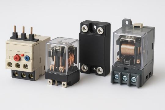
In the complex world of electrical systems, relays play a crucial role in ensuring safety, efficiency, and automation. Among these, low voltage relays stand out as versatile components that manage and protect circuits operating below 1000 volts. Whether in industrial automation, residential power distribution, or commercial infrastructure, these devices act as the nerve center of electrical control and protection.
In this comprehensive guide, we will break down what low voltage relays are, explore their types, explain their functions, and highlight their diverse applications across industries.
What Are Low Voltage Relays?
A low voltage relay is an electrically operated switch that uses a small control voltage (typically below 1000V AC or DC) to switch larger electrical loads on and off. These relays act as intermediaries between control circuits and power circuits, providing isolation, control, and protection.
Unlike manual switches, relays automate the process of circuit management, responding to electrical signals, fault conditions, or system commands without human intervention.
Types of Low Voltage Relays
Low voltage relays come in several forms, each tailored to specific tasks within an electrical system. Here are the main types:
1. Electromechanical Relays (EMRs)
· Use a coil and a movable armature to open or close contacts.
· Provide physical isolation between input and output.
· Common in traditional control panels and basic automation.
2. Solid-State Relays (SSRs)
· Use semiconductors (like thyristors or triacs) instead of mechanical contacts.
· Offer silent operation, faster switching, and longer lifespan.
· Ideal for high-speed applications and environments requiring low maintenance.
3. Overload Relays
· Specifically designed to protect motors and equipment from sustained overcurrent.
· Available as thermal overload relays (using bimetallic strips) or electronic overload relays (using sensors and processors).
4. Time Delay Relays
Provide a deliberate time lag between the relay receiving a signal and switching.
Used in motor control circuits, lighting systems, and sequential operations.
5. Overcurrent and Short-Circuit Relays
· Detect and react to current exceeding preset thresholds.
· Essential for system protection against faults and overloads.
6. Voltage Monitoring Relays
· Monitor voltage levels and trip when voltages fall below or rise above safe limits.
· Protect sensitive devices from under voltage and overvoltage conditions.
Functions of Low Voltage Relays
Low voltage relays serve multiple vital functions in electrical systems:
1. Switching and Control
Relays control the opening and closing of power circuits in response to low voltage signals from controllers, timers, or sensors. This enables remote and automated control of large electrical loads.
2. Protection
Relays detect abnormal conditions like overloads, overcurrent, under voltage, and phase failures. When such conditions arise, they disconnect the affected circuit to prevent equipment damage or fire hazards.
3. Isolation
They electrically isolate control circuits (usually low voltage, low current) from power circuits (high voltage, high current), ensuring safety and reducing interference.
4. Signal Amplification
A small control signal (from a PLC, sensor, or microcontroller) can trigger a relay to switch much larger loads, effectively amplifying the control power.
5. Automation and Sequencing
In complex systems, relays help sequence operations by ensuring that processes occur in the correct order and at the right time intervals.
Applications of Low Voltage Relays
Low voltage relays are the backbone of automation and protection in various industries. Here are some key application areas:
Industrial Automation
· Control of motors, pumps, conveyor belts, and production lines.
· Use in programmable logic controllers (PLCs) and distributed control systems (DCS).
Power Distribution Systems
· Protect electrical panels from overload and short circuits.
· Monitor voltage and current levels in distribution boards.
Building Automation
· Lighting control systems.
· HVAC (heating, ventilation, and air conditioning) systems.
· Elevator and escalator controls.
Renewable Energy Systems
· Manage and protect solar inverters, battery banks, and wind turbines.
· Automatically disconnect faulty sections to prevent system-wide failures.
Data Centers and IT Infrastructure
· Ensure stable power supply to servers and networking equipment.
· Protect sensitive electronics from voltage fluctuations.
Transportation
· Railways, metros, and automotive applications for control and safety circuits.
Home Appliances
· Found in washing machines, microwave ovens, and HVAC units to automate functions and provide protection.
Advantages of Using Low Voltage Relays
· Enhanced Safety: Isolate control and power circuits, reducing electrical shock risks.
· Automation Ready: Easily integrated into automated systems for smarter operation.
· Cost-Effective Protection: Safeguard expensive equipment from damage due to electrical faults.
· Versatile: Available in many forms to suit different voltage levels, currents, and response times.
· Reduced Maintenance: Especially with solid-state relays, which have no moving parts.
Future Trends: Smart Relays and IoT Integration
As industries move toward smart grids and Industry 4.0, low voltage relays are also evolving:
· Digital relays offer programmable settings, self-testing, and event recording.
· IoT-enabled relays can send status updates and alerts to centralized monitoring systems.
· Energy-efficient designs reduce power consumption while providing reliable protection.
Conclusion
Low voltage relays are indispensable in modern electrical engineering, seamlessly combining protection, control, and automation. From safeguarding your home appliances to managing the power in a sprawling industrial plant, these devices ensure that electrical systems run smoothly and safely.
Understanding the different types, functions, and applications of low voltage relays empowers system designers, engineers, and even DIY enthusiasts to build safer and more efficient electrical setups.
As technology advances, the role of these small but mighty devices will only grow, driving the future of safe, smart, and automated power systems.
9 notes
·
View notes
Text
Daneel would totally be able to self-heal minor damage automatically, just like biological entities.
Wrote a bit about heating to heal in No Unnecessary Distinctions!
The team’s “muscle” — or actuator, the part of a robot that converts energy into physical movement — has three layers. The bottom one — the damage detection layer — is a soft electronic skin composed of liquid metal microdroplets embedded in a silicone elastomer. That skin is adhered to the middle layer, the self-healing component, which is a stiff thermoplastic elastomer. On top is the actuation layer, which kick-starts the muscle’s motion when pressurized with water.
To begin the process, the team induces five monitoring currents across the bottom “skin” of the muscle, which is connected to a microcontroller and sensing circuit. Puncture or pressure damage to that layer triggers formation of an electrical network between the traces. The system recognizes this electrical footprint as evidence of damage and subsequently increases the current running through the newly formed electrical network.
This enables that network to function as a local Joule heater, converting the energy of the electric current into heat around the areas of damage. After a few minutes, this heat melts and reprocesses the middle thermoplastic layer, which seals the damage — effectively self-healing the wound.
6 notes
·
View notes
Text
Last time on this blog, I made an ATTINY85 flash an LED
This time I made it turn on two different LED’s with a simple push of a button! (Warning; video has pulsing LED’s)
[VIDEO ID: a breadboard with a PDIP8 ATTINY85 microcontroller on it. There is a button next to it, and two LED'S connecting away from it; A yellow and a green. When the video starts, the yellow turns on, but every time a white human finger pushes and holds the switch, the yellow turns off and the green turns on. END ID]
This program will turn one LED on, but if you push the button it will turn it off and activate the other LED. The LED’s will alternate who’s on and off, and this is directly controlled by the tact switch
This one took a bit to code because I forgot how computers count!! And I knew better too!! I had all the bytes coded for 1,2,3,4 counting when computers count as 0,1,2,3. Very embarrassing 😔 Alas, here’s the assembly code I made for it :)
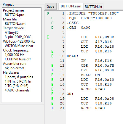
My next step is to make it count two pulses based on a toggled input. While one switch is pushed, count the other switch to see how many pushes it has before the first switch is released. Then, once it gets the count, flash an LED the same number of times.
15 notes
·
View notes
Text
Understanding FPGA Architecture: Key Insights
Introduction to FPGA Architecture
Imagine having a circuit board that you could rewire and reconfigure as many times as you want. This adaptability is exactly what FPGAs offer. The world of electronics often seems complex and intimidating, but understanding FPGA architecture is simpler than you think. Let’s break it down step by step, making it easy for anyone to grasp the key concepts.
What Is an FPGA?
An FPGA, or Field Programmable Gate Array, is a type of integrated circuit that allows users to configure its hardware after manufacturing. Unlike traditional microcontrollers or processors that have fixed functionalities, FPGAs are highly flexible. You can think of them as a blank canvas for electrical circuits, ready to be customized according to your specific needs.
How FPGAs Are Different from CPUs and GPUs
You might wonder how FPGAs compare to CPUs or GPUs, which are more common in everyday devices like computers and gaming consoles. While CPUs are designed to handle general-purpose tasks and GPUs excel at parallel processing, FPGAs stand out because of their configurability. They don’t run pre-defined instructions like CPUs; instead, you configure the hardware directly to perform tasks efficiently.
Basic Building Blocks of an FPGA
To understand how an FPGA works, it’s important to know its basic components. FPGAs are made up of:
Programmable Logic Blocks (PLBs): These are the “brains” of the FPGA, where the logic functions are implemented.
Interconnects: These are the wires that connect the logic blocks.
Input/Output (I/O) blocks: These allow the FPGA to communicate with external devices.
These elements work together to create a flexible platform that can be customized for various applications.
Understanding Programmable Logic Blocks (PLBs)
The heart of an FPGA lies in its programmable logic blocks. These blocks contain the resources needed to implement logic functions, which are essentially the basic operations of any electronic circuit. In an FPGA, PLBs are programmed using hardware description languages (HDLs) like VHDL or Verilog, enabling users to specify how the FPGA should behave for their particular application.
What are Look-Up Tables (LUTs)?
Look-Up Tables (LUTs) are a critical component of the PLBs. Think of them as small memory units that can store predefined outputs for different input combinations. LUTs enable FPGAs to quickly execute logic operations by “looking up” the result of a computation rather than calculating it in real-time. This speeds up performance, making FPGAs efficient at performing complex tasks.
The Role of Flip-Flops in FPGA Architecture
Flip-flops are another essential building block within FPGAs. They are used for storing individual bits of data, which is crucial in sequential logic circuits. By storing and holding values, flip-flops help the FPGA maintain states and execute tasks in a particular order.
Routing and Interconnects: The Backbone of FPGAs
Routing and interconnects within an FPGA are akin to the nervous system in a human body, transmitting signals between different logic blocks. Without this network of connections, the logic blocks would be isolated and unable to communicate, making the FPGA useless. Routing ensures that signals flow correctly from one part of the FPGA to another, enabling the chip to perform coordinated functions.
Why are FPGAs So Versatile?
One of the standout features of FPGAs is their versatility. Whether you're building a 5G communication system, an advanced AI model, or a simple motor controller, an FPGA can be tailored to meet the exact requirements of your application. This versatility stems from the fact that FPGAs can be reprogrammed even after they are deployed, unlike traditional chips that are designed for one specific task.
FPGA Configuration: How Does It Work?
FPGAs are configured through a process called “programming” or “configuration.” This is typically done using a hardware description language like Verilog or VHDL, which allows engineers to specify the desired behavior of the FPGA. Once programmed, the FPGA configures its internal circuitry to match the logic defined in the code, essentially creating a custom-built processor for that particular application.
Real-World Applications of FPGAs
FPGAs are used in a wide range of industries, including:
Telecommunications: FPGAs play a crucial role in 5G networks, enabling fast data processing and efficient signal transmission.
Automotive: In modern vehicles, FPGAs are used for advanced driver assistance systems (ADAS), real-time image processing, and autonomous driving technologies.
Consumer Electronics: From smart TVs to gaming consoles, FPGAs are used to optimize performance in various devices.
Healthcare: Medical devices, such as MRI machines, use FPGAs for real-time image processing and data analysis.
FPGAs vs. ASICs: What’s the Difference?
FPGAs and ASICs (Application-Specific Integrated Circuits) are often compared because they both offer customizable hardware solutions. The key difference is that ASICs are custom-built for a specific task and cannot be reprogrammed after they are manufactured. FPGAs, on the other hand, offer the flexibility of being reconfigurable, making them a more versatile option for many applications.
Benefits of Using FPGAs
There are several benefits to using FPGAs, including:
Flexibility: FPGAs can be reprogrammed even after deployment, making them ideal for applications that may evolve over time.
Parallel Processing: FPGAs excel at performing multiple tasks simultaneously, making them faster for certain operations than CPUs or GPUs.
Customization: FPGAs allow for highly customized solutions, tailored to the specific needs of a project.
Challenges in FPGA Design
While FPGAs offer many advantages, they also come with some challenges:
Complexity: Designing an FPGA requires specialized knowledge of hardware description languages and digital logic.
Cost: FPGAs can be more expensive than traditional microprocessors, especially for small-scale applications.
Power Consumption: FPGAs can consume more power compared to ASICs, especially in high-performance applications.
Conclusion
Understanding FPGA architecture is crucial for anyone interested in modern electronics. These devices provide unmatched flexibility and performance in a variety of industries, from telecommunications to healthcare. Whether you're a tech enthusiast or someone looking to learn more about cutting-edge technology, FPGAs offer a fascinating glimpse into the future of computing.
2 notes
·
View notes
Text
Robotics Project Ideas for All Skill Levels: From Beginner to Advanced
Beginner Projects
Line Following Robot
Description: A robot that follows a pre-defined path marked by a line on the floor. The line can be of any color, but black on a white background is commonly used.
Components: Microcontroller (like Arduino), IR sensors, DC motors, motor driver, chassis, wheels.
Learning Outcomes: Basic electronics, sensor integration, and motor control.
Obstacle Avoidance Robot
Description: A robot designed to navigate its environment and avoid obstacles. It uses sensors to detect objects in its path and changes direction to avoid collisions.
Components: Ultrasonic sensors, microcontroller, motors, motor driver, chassis, wheels.
Learning Outcomes: Understanding of sensor data processing, basic programming, and control systems.
Bluetooth-Controlled Robot
Description: A robot that can be controlled via a smartphone or other Bluetooth-enabled devices. Commands are sent wirelessly to move the robot in different directions.
Components: Bluetooth module, microcontroller, motors, motor driver, chassis, wheels.
Learning Outcomes: Wireless communication, mobile app development, microcontroller programming.
Voice-Controlled Robot
Description: A robot that responds to voice commands, allowing you to control its movements through spoken instructions.
Components: Microphone, speech recognition module, microcontroller, motors, motor driver, chassis, wheels.
Learning Outcomes: Introduction to speech recognition, interfacing sensors, and control mechanisms.
Light Following Robot
Description: A robot that follows a light source. It can be used to follow a flashlight or navigate toward a lighted area.
Components: Light sensors, microcontroller, motors, motor driver, chassis, wheels.
Learning Outcomes: Sensor integration, basic electronics, programming.
Before next read this Robotic Revolution
Intermediate Projects
Self-Balancing Robot
Description: A robot that maintains its balance on two wheels, similar to a Segway. It uses sensors to detect its tilt and adjusts the motors to stay upright.
Components: Gyroscope, accelerometer, microcontroller, motors, motor driver, wheels.
Learning Outcomes: Understanding of feedback control systems, sensor fusion, and motor control.
Robotic Arm
Description: A robotic arm capable of performing simple tasks like picking and placing objects. It can be controlled manually or programmed to follow a sequence of movements.
Components: Servo motors, microcontroller, various sensors (like pressure or touch), structural components.
Learning Outcomes: Kinematics, servo control, programming for sequential tasks.
Maze-Solving Robot
Description: A robot that can navigate through a maze and find the exit. It uses algorithms to decide the best path and avoid dead ends.
Components: IR or ultrasonic sensors, microcontroller, motors, motor driver, chassis, wheels.
Learning Outcomes: Algorithm implementation, sensor data interpretation, navigation strategies.
Remote-Controlled Spy Robot
Description: A small robot equipped with a camera that can be controlled remotely to explore and send live video feed.
Components: Wireless camera, microcontroller, motors, motor driver, chassis, wheels, remote control.
Learning Outcomes: Wireless video transmission, remote control systems, motor and sensor integration.
Line Following Robot with Obstacle Detection
Description: A robot that not only follows a line but also detects and avoids obstacles on its path. It combines line following and obstacle avoidance features.
Components: IR sensors, ultrasonic sensors, microcontroller, motors, motor driver, chassis, wheels.
Learning Outcomes: Integration of multiple sensor data, complex programming logic, advanced control systems.
Advanced Projects
Humanoid Robot
Description: A robot designed to resemble a human body. It can perform tasks like walking, speaking, and interacting with its environment.
Components: Servo motors, microcontroller, sensors (accelerometer, gyroscope), structural components.
Learning Outcomes: Advanced kinematics, complex control algorithms, humanoid robotics.
Autonomous Delivery Robot
Description: A robot that can autonomously navigate to deliver packages within a designated area. It uses GPS and other sensors to determine its location and avoid obstacles.
Components: GPS module, ultrasonic sensors, camera, microcontroller, motors, motor driver, chassis, wheels.
Learning Outcomes: Autonomous navigation, path planning, integration of multiple sensors.
Robotic Exoskeleton
Description: A wearable robotic suit that can assist with movement, enhancing the strength and endurance of the user.
Components: Servo motors, sensors (like pressure, motion), microcontroller, structural components.
Learning Outcomes: Biomechanics, actuator control, wearable robotics.
Quadruped Robot
Description: A four-legged robot capable of walking, running, and navigating various terrains. It mimics the movement of animals like dogs or cats.
Components: Servo motors, microcontroller, sensors (accelerometer, gyroscope), structural components.
Learning Outcomes: Gait analysis, dynamic stability, complex movement programming.
Swarm Robotics
Description: A group of small robots that work together to complete tasks. They communicate and coordinate to achieve goals like collective exploration or object transport.
Components: Multiple small robots, communication modules, microcontroller, various sensors.
Learning Outcomes: Distributed systems, communication protocols, cooperative robotics.
2 notes
·
View notes
Text
LED displays are the easiest parts on which to identify the pins when you don't have any information on their pinouts, but they're still very satisfying to get working.
See, I've got a couple of cute little displays with no accompanying data:

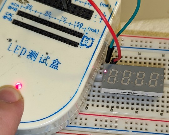
The number on the side isn't an identifiable part number, and the markings on the other side — "07817N" — is more likely a date code or batch number than anything else. With this many segments and 24 pins, it's likely either a common-cathode or common-anode device, and not a matrix, so that's somewhere to start; I popped one into a breadboard and started probing with a little LED tester and some jumper wires. The first few pins I tested turned up some red light, so that was very encouraging.
It turned out to be a common cathode device, mostly.

A single-digit common cathode display works like this: you ground the single wire for the whole display — the common cathode of all the LEDs — and supply voltage to each segment's anode. So to make a three on one of these, you put the voltage into the anodes for segments a, b, c, d, and g, and to turn the whole thing off, you stop grounding the cathode.
A multidigit common cathode display works the same way, but all the identically named segment displays are tied together. You usually need a microcontroller to manage the timing, but you have it ground the cathode for the digit and light up the segments, then stop, unground it, and do the same for the next digit. You can't light them with different layouts at the same time, but thanks to human persistence of vision, you don't have to. You just loop through really fast and it looks like it stays lit. On this one, pins 2, 5, 8, and 10 are the cathodes for digits 1-4 respectively, and the pins for segments a-g are 17, 19, 20, 3, 11, 18, and 22. The decimal points for digits 1-3 have their anode at pin 9, while the one for digit 4 (the bottom of the final three dots on the display) is on pin 16 for some reason.
But while the device I have operates like that for the digits, the dots are handled a little differently. The first three are an independent common cathode display, with individual segment pins that aren't connected to anything else (CC on 24, with a on 23, b on 4, and c on 1), and the top two of the last three are the same way (CC on 15, top on 13, middle on 14). The top dots of the middle colons are independent LEDs — the first has its cathode at 12 and anode at 21, and the second has its cathode at 7 and anode at 6.
I'd show off the thing working if it didn't mean breaking out an Arduino board and hooking it to at minimum 11 patch wires. I don't actually have an immediate use for these. I should figure out something synthesizer related that could make use of a wall clock.
6 notes
·
View notes
Text

The TTP224 is a 4-Channel Touch Sensor, meaning it has four touchpads. Whenever a capacitive load such as human hands is brought in proximity with the sense pad, the sensor then senses the change in capacitance and activates the switch. Custom sense-pads can be made from nearly any conductive material and these sensors can detect touch through thin layers of non-conductive materials such as glass, plastic, fabric or even wood. Each Touchpad has its respective output pin when the user touches a pad, the corresponding output pin will go high. It is very easy to interface with microcontrollers like Arduino to control different applications as a switch. It can be used in home automation, motor control, Relay control, etc. the module basically gets rid of the push button troubles.
6 notes
·
View notes
Text
I don't, actually. Like, I understand the rocks we tricked into doing math on multiple levels. I had a whole job, where for a bit, I had to figure out what other people's programs did only given the binary. And in that same job-- I had a thing for a bit where I had to understand how an earlier version of the CPU in every PC behaved-- so that it could be replicated by programs people wrote. I've gone through and soldered a bunch of things to a micro-controller and wrote code to make all of those things DO what I wanted. Like, code that makes things go IRL. (The thing I remember most-- was waiting for a particular point in time to rotate a shutter because it was on a telescope pointed at the sun for last year's solar eclipse. I wanted it to track north using a compass and GPS and then visually track the sun, but that took more time than I had to solve problems. ) I have a thing in my pocket that can access all human knowledge and can be used to watch my lizard son with a frequency of light neither of us can perceive as he crawls around? I still call that a cell phone But the fact that the CPU, the microcontroller, and the cell phone are so many things that got shoved together and do things like they do? It's still Magic.
Addendum: look at the way people treat nuclear energy.
a pet peeve of mine in fantasy is when they talk about the Magic(tm) like studying the magic, having the magic, or like, supernatural powers but where everyone has superpowers in that civilization. and. and.
elves wouldn't say "we have superior vision", they'd say "yeah humans are practically blind".
in my pocket i have a piece of metal with a little window that is powered by the energy of running water and that contains all the information in the world
and we call that a cell phone. i play project makeover on mine.
any animal would call that Magic(tm). be we don't. because it's not magic for us.
do you get me?
#it didn't stop being magic because i understood it#it started being more magic#maybe because I understand there are so many ways it couldn't
7K notes
·
View notes
Text
From Classroom to Lab: Exploring SUAS’s Specialized Robotics & Automation Labs

At the heart of engineering excellence is the ability to build, test, and innovate — and that’s exactly what students at Symbiosis University of Applied Sciences, Indore (SUAS) experience every day. As a modern private university in Indore, SUAS blends academic knowledge with practical expertise, especially in its B.Tech in Automation & Robotics program. But what truly sets SUAS apart is its world-class laboratory infrastructure, designed to mirror the most advanced industry settings.
Real-World Learning Begins in the Lab
While many universities emphasize theory, Indore Symbiosis focuses on real-world application. Students spend a significant portion of their time in specialized labs, engaging with the same equipment, tools, and technologies used by industry professionals. SUAS follows a 70:30 model — 70% practical learning and 30% theoretical instruction — making it one of the top universities in Indore for hands-on engineering education.
Key Laboratories at SUAS
🔧 Automation Lab
This lab gives students access to industrial automation components like programmable logic controllers (PLCs), human-machine interfaces (HMIs), sensors, and actuators. Here, students simulate and implement automated systems just as they would in automotive, manufacturing, or packaging industries.
🤖 Robotics Lab
Equipped with robotic arms, Arduino kits, and programmable systems, this lab allows students to build and test robots from scratch. They learn everything from robotic movement and path planning to vision-guided robotics and AI integration.
⚙️ Microprocessors & Embedded Systems Lab
Students get hands-on with microcontrollers like 8051, PIC, and ARM boards, learning how to build embedded systems — the backbone of smart robots and automation devices. The lab supports courses in embedded C, IoT systems, and device-level programming.
🛠️ Lucas-Nülle Lab Setup
Through international collaboration, SUAS integrates Lucas-Nülle’s Germany-based training systems, known for bridging academic learning with practical engineering. These systems simulate real industrial environments and enhance technical training to a global standard.
Innovation Starts Here
Labs at SUAS are not just for coursework. Students regularly use them for capstone projects, hackathons, and startup prototypes — from 3D-printed robotic parts to drones and home automation systems. Supported by SUAS’s incubation center and mentorship programs, students can transform classroom ideas into real innovations.
Why It Matters
In a field like automation and robotics, real lab exposure gives students a serious edge. They not only understand theoretical models but can also wire, program, and troubleshoot physical systems — a skillset highly prized by employers in India and abroad.
Conclusion
For aspiring engineers seeking the perfect blend of academic learning and hands-on experience, Symbiosis University of Applied Sciences, Indore delivers through its specialized labs and industry-driven curriculum. It’s no wonder SUAS is widely regarded as one of the best universities in Indore for engineering in the automation era.
0 notes
Text
Enhancing Spring Quality Control with Star EMBSYS Spring Testing Machines
In today’s precision-driven manufacturing environment, the demand for reliable and accurate testing equipment has never been greater. Springs, being critical components in various mechanical assemblies, must undergo rigorous testing to ensure durability, flexibility, and performance under load. A spring testing machine is essential for evaluating these parameters. Among the notable names in this domain, Star EMBSYS has established itself as a trusted provider of high-quality, technologically advanced spring testing machines that cater to a wide range of industrial needs.
Advanced Technology for Accurate Spring Testing
Star EMBSYS spring testing machines are engineered to deliver precise measurements of compression, tension, and torsion in springs. With increasing demands from automotive, aerospace, electrical, and consumer goods industries, manufacturers need to ensure that every spring meets stringent performance standards. Star EMBSYS addresses this requirement through machines equipped with digital force indicators, load cells, and advanced software integration.
The machines allow for real-time data acquisition, digital calibration, and detailed performance analytics, all of which contribute to enhanced quality assurance processes. Their models offer programmable test cycles, auto peak hold functions, and adjustable testing speeds, making them suitable for both research labs and production floors. The use of microcontroller-based technology ensures consistent readings and minimal human error, reinforcing Star EMBSYS’s reputation for delivering accuracy and reliability.
Custom Solutions and Industry Applications
What sets Star EMBSYS apart is its ability to provide customized solutions tailored to specific industrial requirements. Whether it’s a standard compression spring for shock absorbers or a specialized torsion spring in aerospace assemblies, Star EMBSYS machines can be adapted to test various spring types and sizes. This level of flexibility is crucial for companies that manufacture springs in different configurations and strengths.
The versatility of their machines extends beyond technical features. Star EMBSYS also emphasizes user-friendly interfaces, intuitive controls, and robust after-sales support—components that contribute to operational efficiency and reduced training time. Additionally, their spring testing machines are built with durable materials, ensuring long-term use with minimal maintenance.
Industries that rely heavily on quality spring components—such as automotive OEMs, defense contractors, and electronics manufacturers—benefit immensely from integrating Star EMBSYS testing machines into their production and QA pipelines. By improving the repeatability and accuracy of tests, these businesses not only enhance product quality but also reduce operational costs caused by faulty components.
Conclusion
In a market where precision and performance are critical, Star EMBSYS spring testing machines stand out as an essential investment for manufacturers aiming to uphold product integrity and operational efficiency. Their commitment to innovation, customization, and support makes them a preferred partner for industries demanding the highest standards in spring testing. Businesses looking to streamline quality control and gain a competitive edge will find Star EMBSYS a reliable and forward-thinking ally.
Visit:- https://www.starembsys.com/spring-testing-machine.html
0 notes
Text
The Future of Warehouse Robots: AI Meets Electronics Design

The future of warehouse robots lies in the powerful fusion of AI integration and advanced electronics design — enabling smarter, faster, and more autonomous logistics operations. Electronics design ensures robots are compact, reliable, and capable of processing massive amounts of real-time data, while AI adds the intelligence to learn, adapt, and optimize warehouse tasks like sorting, picking, and navigating.
If you’re looking to understand what’s driving the next wave of innovation in warehouse automation, this article explains how AI and electronics are shaping the most efficient, intelligent robots ever built for industrial logistics.
Why AI and Electronics Design Are Game Changers for Warehouse Robots
Warehouses are fast-paced environments where precision, speed, and adaptability are critical. Traditional automation helped, but it lacked flexibility. Today, AI-driven warehouse robots powered by advanced electronics design are bridging that gap.
Here’s how the synergy works:
Electronics design enables lightweight, high-performance robotic systems with smart sensors, efficient power management, and robust connectivity.
AI integration processes that data to make decisions, learn from patterns, and continually improve task efficiency.
Together, they create autonomous systems capable of handling unpredictable inventory challenges in real time — faster and more reliably than ever.
Core Technologies Behind Modern Warehouse Robots
1. Smart Electronics Design
At the heart of every capable warehouse robot is a custom-designed electronic system, which includes:
Embedded microcontrollers and PCBs that control movement and communication
Sensor arrays for object detection, spatial awareness, and load tracking
Battery and power systems optimized for long shifts and fast recharging
Wireless modules for seamless data flow and remote updates
Electronics design focuses on reliability, low power consumption, and miniaturization — making robots both powerful and space-efficient.
2. AI Integration
AI gives robots the intelligence they need to:
Identify and classify objects with computer vision
Plan routes dynamically using real-time mapping and SLAM (Simultaneous Localization and Mapping)
Predict demand and optimize picking paths
Detect anomalies or safety risks without human intervention
This AI capability is only possible when backed by well-integrated, high-speed electronics that deliver real-time data and process it on-board or via edge computing.
Key Applications in Warehouses
Autonomous Mobile Robots (AMRs)
AI-powered AMRs use advanced sensors and AI algorithms to navigate warehouse floors, avoiding obstacles, rerouting in real-time, and managing deliveries.
Electronics role: Precise motor control, LiDAR/ultrasonic sensor support, real-time feedback, and robust safety circuits.
Robotic Picking Systems
Robots with grippers or suction arms can now pick and sort items of various shapes, guided by AI vision systems.
Electronics role: High-speed processors, smart camera modules, and force-sensitive feedback loops.
Inventory Monitoring Robots
Some robots autonomously scan shelves for stock levels, damaged goods, or misplaced items.

Benefits of AI + Electronics in Warehouse Robots
Greater Efficiency: AI algorithms optimize paths, reduce downtime, and adapt to demand.
Higher Accuracy: Fewer picking or sorting errors thanks to smart sensing and decision-making.
Scalability: Modular electronics design makes it easier to upgrade or expand systems.
24/7 Operation: Smart electronics allow continuous performance with minimal maintenance.
Reduced Labor Costs: Automation reduces reliance on manual labor for repetitive tasks.
Challenges in Design and Integration
While the benefits are clear, building next-gen warehouse robots isn’t without challenges:
Power constraints: AI processing requires energy; electronics must balance performance with battery life.
Sensor fusion complexity: Integrating multiple sensors into one coherent decision-making unit is tricky.
Thermal management: AI chips and motors generate heat, requiring clever thermal design.
Cybersecurity: Wireless communication and AI models must be protected from external threats.
These issues highlight the importance of precise, efficient electronics design and secure, robust AI models.
Future Trends to Watch
Edge AI for Faster Decisions
Instead of sending data to the cloud, AI processing is moving closer to the source (onboard). This requires faster processors and optimized electronics design to deliver near-instant results.
Swarm Robotics
Using multiple robots that coordinate like a hive mind, enabled by AI and synchronized electronics, to cover large warehouse spaces efficiently.
Predictive Maintenance
AI models will monitor wear-and-tear data from sensors to predict breakdowns before they happen — enabled by electronics that track vibration, temperature, or usage cycles.
Interoperability Standards
Future electronics design will focus on plug-and-play compatibility, allowing various robots to work in harmony across brands and platforms.
Real-World Example: AI-Powered Fulfillment Centers
Major players like Amazon and Alibaba already deploy hundreds of AI-integrated warehouse robots designed with advanced electronics systems. These robots:
Navigate high-density shelf areas
Communicate with human operators and other robots
Pick, sort, and deliver packages continuously
Adapt operations based on live order data
This synergy between electronics design and AI has helped these companies achieve previously impossible levels of speed and accuracy.
Final Thoughts
The future of warehouse robots is already taking shape — and it’s built on two pillars: brilliant electronics design and seamless AI integration. Together, they unlock the full potential of automation, allowing warehouse robots to think, adapt, and perform with superhuman precision.
For logistics leaders, engineers, and businesses looking to stay competitive, investing in this technology isn’t optional — it’s a strategic advantage. As innovation accelerates, expect to see even more intelligent, flexible, and efficient warehouse robots shaping the next generation of industrial success.
#ElectronicManufacturing#EMSIndia#PCBDesignChennai#ElectronicsInChennai#PCBAIndia#SMTAssembly#ElectronicsManufacturingServices#PCBManufacturingIndia#ChennaiEMS#ManufacturingInChennai
0 notes
Text
Arduino is essentially a language designed for interacting with and operating interactive objects and digital devices. Arduino has immense potential, since it’s being increasing used for controlling remote controlled objects such as drones. If you are looking for a book on Arduino, this article will serve as the base for taking a decision and choosing the right book that will help you sharpen your skill in Arduino. This article will give you information about seven best Arduino books that are regarded as featured books. Arduino is open source software (IDE) which makes it a breeze to write as well as upload codes to a board. Moreover, Arduino runs on Mac OS X, Linux as well as Windows. The environment of Arduino is written in Java language; also it’s based on open-source software and processing. Take help of the information furnished in the books and explore the horizon of Arduino programming. Programming Arduino Getting Started with Sketches (By: Simon Monk ) Learn Arduino programming with ease with the easy-to-follow and clear examples featured in the book. The book contains the software side of Arduino and describes the way of writing the program using the well-crafted sketches using modified C programming language meant for Arduino. The book features downloadable sample programs that can be modified as per your requirement. The easy explanation and details crafted in the book make is one of the best books to learn Arduino. You can structure your data by using strings and arrays. The book also helps you learn how to use digital and analog inputs and outputs of Arduino in the programs. Programming Arduino Next Steps: Going Further with Sketches (By: Simon Monk ) This is the second book of the series that makes you understand the next step of the beginner’s guide. You can take your Arduino understanding and skills to the next level with this easy-to-study book. This book on Arduino basically is a practical guide and the secret of the professional Arduino programming is revealed by electronics guru Simon Monk taking every possible aspect under the hood. The book features the coverage of Arduino Uno, Due Boards and Leonardo. This book is all-in-one repository and features more than 75 examples and sketches. Exploring Arduino: Tools and Techniques for Engineering Wizardry (By: Jeremy Blum ) This book is the best book as far as the third step is concerned – understanding the tools and techniques of Arduino. This book is all about that and helps you learning to build robots, gizmos and gadgets using Arduino. This book is written by Jeremy Blum – the Arduino expert – and is a unique book that uses the popular Arduino microcontroller platform, which is an instrument that teaches you about programming, electrical engineering and also human-computer interaction. Beginning C for Arduino: Learn C Programming for the Arduino (Technology in Action) (By: Jack Purdum ) This is the Arduino best book for those who do not have prior experience in programming of microcontrollers. This book is written so well and in easy-to-understand way that it helps the readers to understand the aspects of Arduino and help them learn as well and experiment. This book starts with an introduction to C language and reinforces every programming structure using simple demonstrations. Author Jack Purdum has used a very engaging style of writing in order to teach good and efficient techniques of programming. Arduino Workshop: A Hands-On Introduction with 65 Projects (By: John Boxall ) This book offers hands-on experience on Arduino programming with 65 projects. With the help of this book, you can learn the basics of Arduino programming, build a project after learning and finally create your own Arduino program. Arduino is basically an easy, flexible, cheap and open source microcontroller programming platform that offers students to learn and create their own homemade projects and this book is the best one in this category. This book
gives you an opportunity to learn and create devices using almost unlimited range of input and output sensors, displays, indicators or add-ons. Arduino For Dummies (By: John Nussey ) Arduino is not just an ordinary circuit board and corresponding software. It does not matter whether you are a designer, artist, hobbyist or a programmer, Arduino enables you to play with electronics. This book helps you learn building a variety of circuits that can control or sense things in the real world. If you have loads of ideas that you want to bring to the real world or you have curiosity to know and learn the possibilities, this book is perfect for you to read. The best part about this book is that it enables you to learn by writing the programs in real time. Arduino Cookbook (By: Michael Margolis ) Do you want to build devices that can interact with the real world? This cookbook is the perfect answer to that question. This is book is an all-in-one cookbook for you if you want to experiment with popular Arduino programming or microcontroller environment. The book offers more than 200 techniques and tips in order to build a variety of objects and prototypes like robots, detectors and toys along with interactive clothing, which sense and respond to light, heat, position, sound and touch.
0 notes
Text
Matrix Connection: Few Pins, Many Options

4+4=8, 4×4=16. It often happens that a microcontroller or other chip has too few pins. You can use a more complex and expensive microcontroller, or you can multiplex the pins. Today I will describe one of the ways to do this.
In previous posts, we have already talked about decoders and demultiplexers, as well as shift registers.
In the first case, an n-bit binary number can point to one of the decoder outputs, the number of which is equal to two to the power of n.
For example, the 74HC138 3:8 demultiplexer chip allows you to light up eight LEDs or turn on eight relays using only three microcontroller pins or three communication wires between devices.

However, this scheme does not allow activating several outputs simultaneously. In the case of LEDs, we can take advantage of the persistence of human vision and constantly send different numbers to the inputs of the 74HC138. If the frequency of numbers changing exceeds 24 hertz, then it will seem to us that from 0 to 8 LEDs are lit simultaneously and continuously.
It should be noted that the more LEDs are used, the dimmer each of them will be. Although in some cases this is a good thing, the consistency of the overall brightness means that when more LEDs are turned on, they will not be blinding.
It is also possible to turn on several relays simultaneously through a decoder, although it is more difficult. Timing circuits similar to those used in running lights with slowly dimming LEDs will be required.

Thanks to diodes with RC circuits at the bases of transistors, relay coils connected instead of LEDs will switch off not at the same moment as the signal disappears from the decoder output but after a certain period of time.
If you keep the capacitor charged by periodically applying the corresponding number to the decoder input, the relay remains on. If you stop transmitting this number, the relay will turn off.
This is very similar to the operation of the Williams-Kilburn tube, one of the first types of computer memory in history. The electron beam scanned the cathode-ray tube screen, just like a television.

To turn the indicator into a storage device, engineers simply added a matrix of electrodes onto the screen and synchronized the modulation of the beam with the scanning of this matrix. Those areas of the glass where the electrons hit acquired a charge that would fade if not renewed.
Of course, this was not a fast memory by any stretch. And controlling a relay via an RC chain is also not fast. However, it fits a number of applications.
Each additional wire or microcontroller pin doubles the capacity of the demultiplexer. For example, 4 bits give 16 outputs. But the required number of decoder chips also doubles. For 4:16 you need two 3:8 chips, for 5:32 you need four, and for 6:64 as many as eight, and so on.

But the shift register allows you to transmit or read practically an unlimited number of binary bits using only three wires: one for data, one for clocking, and one for register latching.

Therefore, when paired with microcontrollers, to expand the number of pins, shift registers are most often used rather than demultiplexers.
Two CD4017 decimal counter-decoders have 2×10=20 outputs. But if you make a matrix where one chip scans the rows and the second the columns, you get 10×10=100. Or 9×9=81, as done in this matrix LED effect.

The same design is used in an electronic timer, where 6×10=60 LEDs are placed around the circumference of the dial and serve as the second hand.

As you can see, the matrix is not necessarily square or rectangular. It can be stretched into a line or closed into a circle, and in general, its elements can be arranged in the shape you need.

The decade counter U2 receives timing signals with a frequency of 1 hertz from the generator on the 555 timer. Using switch SW1, you can switch the chip to 'disable counting' mode, which means a pause in the stopwatch operation.
U2 counts to ten (from Q0 to Q9) and transmits the CARRY-OUT signal to the clock input of U1. Note that CARRY-OUT goes to logical zero when the counter has counted to Q5, and to logical one at the moment of overflow, when Q0 is activated again after Q9.

The CD4017 chip reacts just to the transition from low to high, so U1 will turn on the next row of LEDs exactly when U2 has turned off column Q9 and turned on Q0.
The active voltage level at the outputs Q0..Q9 of the CD4017 counter is high, and the current in the LED should flow from plus to minus, from anode to cathode, in the direction of the arrow. Therefore, the signals from the U2 outputs are inverted by the U3 CD4069 chip.
This chip contains six logic inverters. To count 60=10×6 seconds, we just need 6 lines of 10 LEDs. On the diagram, they look like rows and columns, but on the board, they are placed around the circumference of the dial.
After a minute has passed and Q2 has counted to Q6, transistor Q1 opens through resistor R2, performing two actions in our circuit.
First, it charges the capacitor C1, the voltage across which turns on transistor Q2 through resistor R3. This is exactly the same scheme that we've discussed above.
While C1 is discharging, the BZ1 buzzer will beep, not continuously but in 1 hertz pulses, since the positive terminal of BZ1 is connected not to the positive power supply terminal but to the output of the second pulse generator.
An asymmetrical flip-flop is constructed on transistors Q3 and Q4. A logical one from capacitor C1 through diode D1 and resistor R4, or from the power supply positive through R5 and button SW3, sets the flip-flop to one, which goes to the reset input of both counters, stopping the counting and resetting them to zero.
The diode is needed so that the buzzer is triggered only at the end of the count, not when the STOP button is pressed or a logical one appears at the output of the trigger through resistor R6, which latches the trigger into a high- or low-level state.
Button SW2 resets the trigger and starts the second count. If you made a multi-position switch that allowed you to choose which of the Q1..Q6 pins to connect R2 to, the timer could count not only up to 60 but also up to 10, 20, 30, 40, and 50 seconds.
And the last circuit for today is an RGB running light. Here IC1 is the familiar CD4060 binary counter, and 74HC138 is a 3:8 decoder that lights up one of the eight LEDs, LED1..LED8.

These are RGB LEDs, and the light color will depend on the state of the outputs Q8–Q10 of the IC1 chip.
000: white; all channels are on
001: blue-green
010: magenta; blue plus red
011: blue
100: yellow; red plus green
101: green
110: red
111: LEDs do not light up
As you can see, even to control RGB LEDs, it is not at all necessary to use a microcontroller. With two simple chips and three transistors, you can create the beautiful effect of a running, color-changing light.
0 notes
Text
Understanding Mechatronics: A Beginner’s Guide for Freshers
If you’ve just stepped into the world of engineering or are considering which specialization to pursue, you might have come across the term Mechatronics. It sounds futuristic—and honestly, it is. But what exactly is it? Is it mechanical? Is it electronics? Or is it something else altogether?
Let’s break it down and make it simple for you.
What Is Mechatronics?
Mechatronics is an interdisciplinary field that blends mechanical engineering, electronics, computer science, and control engineering. It’s all about designing and creating smarter machines—systems that not only move or perform tasks but also think and respond intelligently.
Think of things like self-driving cars, robotic arms in factories, automated coffee machines, or even drones that maintain stability mid-air. All of these rely on the principles of mechatronics.
This discipline is becoming essential in today’s automation-driven world, especially with the rise of Industry 4.0, where machines communicate with each other to optimize performance without human input.
Why Should You Care as a Fresher?
In the early stages of your engineering journey, it's important to understand where the future is headed. Mechatronics is one of those areas that’s not just growing—it’s exploding.
As a fresher, you might still be figuring out what excites you most. But if you're someone who enjoys blending creativity with technology—imagine coding a program and then watching it control a real robot—this field will likely click with you.
Also, if you eventually want to work in automation, AI-driven systems, or robotics, mechatronics offers you the foundation and flexibility to go in multiple directions.
What Will You Learn in Mechatronics?
Typically, if you pursue mechatronics as a core subject or even as an elective, you’ll dive into areas like:
Sensors and Actuators: Devices that help machines sense their environment and act accordingly.
Microcontrollers and Embedded Systems: The brains of most modern electronic machines.
Mechanical Design: Basics of gears, motors, and structures that move.
Control Systems: How to ensure a robot does what it’s supposed to—no more, no less.
Programming: Often in C/C++ or Python to control the devices.
You may also get your hands on software like MATLAB, Simulink, or Arduino IDE early on.
How to Get Started in College
You don't have to wait till the third year to explore mechatronics. In fact, some colleges start offering related workshops and certifications right from the first year. If you're studying in a place where the labs are well-equipped and faculty are research-active, you'll probably get the chance to work on actual robots or automation systems before you graduate.
During a visit to a lab at NMIET Bhubaneswar, I noticed students working on automated vehicle prototypes that used sensors for obstacle detection. It struck me how mechatronics isn’t just a theoretical subject in such institutions—it’s hands-on and real.
Career Scope: Where Can Mechatronics Take You?
Mechatronics engineers are highly valued in sectors like:
Robotics and Automation
Aerospace
Automobile Manufacturing
Medical Equipment Development
Home Automation and Smart Devices
With increasing reliance on smart systems and AI-driven hardware, companies are actively seeking engineers who can work across domains. This is where mechatronics gives you a massive edge.
Even core mechanical or electrical engineers are now advised to pick up basic knowledge of microcontrollers or coding. So, if you're already in a college that encourages learning beyond your core, you're in the right place.
What Makes a Good College for Mechatronics Learning?
Let’s be honest—your learning environment plays a big role. Access to automation labs, exposure to industry tools, faculty who encourage innovation, and the chance to work on real-world projects—these are the things that matter most.
Some of the top engineering colleges in Odisha are already introducing mechatronics modules in mechanical and electronics streams. The goal is to create engineers who can build, code, and innovate.
It’s always a good idea to look into whether the institute collaborates with industries for internships and whether they have tie-ups for campus placements with companies involved in automation or robotics.
Final Thoughts: A Future-Proof Path
Mechatronics is not just another subject—it’s a mindset. It teaches you to look at machines not just as static components, but as intelligent systems that interact with the world.
As a fresher, you don’t need to master it all at once. Start with basic projects—maybe build a line-follower robot or an automatic light system. Join clubs, take up online certifications, and most importantly, stay curious.
If you’re in an environment where creativity and cross-disciplinary learning are encouraged—like the one I saw at NMIET—you’re already ahead of the curve.
So, if you’re dreaming of working on robots, smart devices, or even futuristic innovations we haven’t seen yet—mechatronics might just be the path you’ve been looking for.
#bhubaneswar b tech colleges#college of engineering bhubaneswar#best engineering colleges in orissa#best engineering colleges in bhubaneswar#best private engineering colleges in odisha#best engineering colleges in odisha
0 notes